


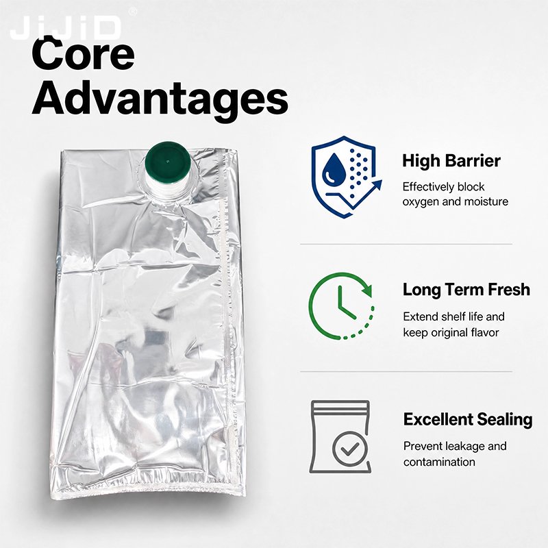
Aseptic Bag Specifications V2.2 (February 2026) – Complete Overview
This document provides the complete technical specifications for aseptic bags as defined by Aseptic Bag Manufacturers Association version 2.2, dated February 2026. These guidelines cover standard bag sizes, fitment types, barrier film options, irradiation requirements, packaging, marking, and documentation – all essential for ensuring safe, reliable use in food and beverage filling applications.
Standard Bag Sizes (All Internal Dimensions)
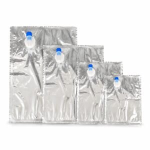
Small Bags (up to 30 litres)
Dimensions should be matched to the outer container so that the outer support provides adequate mechanical protection under service conditions.
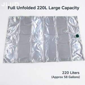
200 & 220 litres (55 & 60 gallons) – horizontal filling (conveyor belt / conical drum)
-
Size: 890 (±15) × 1560 (±15) mm
-
Spout: 1″
-
Position: centre, 150 mm (±15) mm from the inner edge of the top seal
-
Filling mode: conveyor belt / horizontal for old and new conical drum types
200 & 220 litres (55 & 60 gallons) – vertical filling (direct into drum)
-
Size: 890 (±15) × 1560 (±15) mm
-
Spout: 1″
-
Position: centre, 60–80 mm (±15) mm from the inner edge of the top seal
-
Filling mode: direct into drum / vertical for old and new conical drum types
1000 & 1200 litres (300 gallons) – standard bin
-
Size: 2060 (±20) × 2160 (±20) mm
-
Spout: 1″
-
Position: bag centre (±30 mm)
-
Standard bin internal dimensions: Length 1143 mm, width 1041 mm, height 990 mm
1400 litres (330 gallons)
-
Size: 2400 (±20) × 2080 (±20) mm
-
Spout position: bag centre (±30 mm)
800 litres
-
Size: 2050 (±20) × 1800 (±20) mm
-
Spout: 1″
-
Position: bag centre (±30 mm)
Laboratory bags
-
1–5 litres (depending on filler type)
-
Other sizes and film constructions available on request.
Important Notes
-
A further tolerance of ±10 mm is permissible on top of the nominal values stated above.
-
For dispensing applications where two fitments are used (one for filling, one for dispensing), the position of the dispensing spout should be agreed with the supplier; the filling spout position remains as specified.
-
All bag dimensions must be cross‑checked with the outer packaging dimensions – consult your supplier for details.
-
Spout location must be verified with the supplier according to the filling head specifications.
-
For product sampling, high‑oxygen‑barrier bags should always be used.
Fitment (Spout) Types
1) Heat‑resistant types (max. temperature up to 105 °C)
-
a) Short neck plug fitment, 1″
-
b) Long neck flat cap, 1″
-
c) Flat cap, 2″
-
d) Pierce‑through tap, 2″
-
e) Pierce‑through tap, 3″
-
f) Discharge valve, 2″
For applications requiring temperatures above 105 °C, please contact the bag manufacturer for custom solutions.
2) Non‑heat‑resistant types (max. temperature up to 65 °C)
-
a) High‑rise spout with 1″ flat cap
-
b) High‑rise spout with flexible 1″ soft cap
Standard Barrier Films
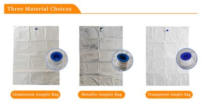
1) M‑Metallized barrier films (typical values)
-
Oxygen transmission rate (OTR): < 1 cc/m²/24 h (Oxtran, 23 °C, 75% RH, measured on unflexed laminate)
-
Tensile strength over welds: 50 N (MD and TD) – sample size 2 × 30 mm, 15 mm width
-
Corrosion resistance: delamination (loss of aluminium) shall not exceed 2 mm from the exposed edge after 24 hours in a hypochlorite solution (200 ppm chlorine, buffered to pH 6–8, at 20–25 °C)
2) T‑Transparent EVOH‑based barrier films (typical values)
-
Oxygen transmission rate (OTR): < 2 cc/m²/24 h (Oxtran, 23 °C, 75% RH, measured on unflexed film)
-
Tensile strength over welds: 40 N (MD and TD) – sample size 2 × 30 mm, 15 mm width
3) F‑Aluminium foil‑based films (typical values)
-
Oxygen transmission rate (OTR): < 0.02 cc/m²/24 h (Oxtran, 23 °C, 75% RH, measured on unflexed laminate)
-
Tensile strength over welds: 50 N (MD and TD) – sample size 2 × 30 mm, 15 mm width
-
Corrosion resistance: same delamination limit as M‑films (≤ 2 mm) under the same hypochlorite test conditions.
Film Combinations
-
Multiple film layers may be combined to achieve higher barrier levels. The inner layer may be barrier (T) or polyethylene. EVOH film as the inner layer in direct contact with the product is not recommended.
-
Example: M‑T film structure can provide OTR < 0.5 cc/m²/24 h at 23 °C and 75% RH.
Note: Oxygen transmission rate measured according to ASTM D3985 standards.
Important: Any leakage of steam from the filling chamber may cause film damage.
Bag Irradiation
-
Usual irradiation dosage: 15 kGray (gamma or X‑ray).
-
This dosage level may vary according to local regulatory requirements – always confirm with local specifications.
-
Irradiation indicators must be present on both the instruction leaflet (placed inside shipping boxes) and on the outer shipping boxes. The indicator must be red in colour.
